")
")
It is a physical instrument that allows you to observe the trajectories of electrically charged particles. There are two types of cloud chambers: the Wilson expansion cloud chamber (1911) and the Langsdorf diffusion cloud chamber (1939). In this paper I will discuss the design of the diffuse cloud chamber and the experiments.
Content
- Cloud chamber – History
- Diffusion cloud chamber (my construction)
- What particles can we see there ?
- Radioactive objects and uranium minerals in the cloud chamber
- Interaction of electromagnetic radiation – X-rays and gamma rays in a cloud chamber
- Final video compilation of the whole cloud chamber project
Surface contamination by Radon-220 daughter decay elements – another article and an observation experiment in a diffuse cloud chamber
Cloud chamber – History
It is a physical instrument that allows you to observe the trajectories of electrically charged particles. There are two types of cloud chambers: the Wilson expansion cloud chamber (1911) and the Langsdorf diffusion cloud chamber (1939).
Wilson expansion cloud chamber (1911)
It is a container with a piston filled with clean air and water vapour. In today's small balloon demonstration chambers, other mixtures are also used, e.g. with acetone, ethyl alcohol and water. Other gases are also used in practice as chamber filler at different pressures. When the piston is released sharply, the gas expands and its temperature drops. The supersaturation state is achieved in this type of chamber by adiabatic expansion of the working piston, which produces a strong supersaturation of duration not exceeding 0.2s. The steam is saturated but has nothing to condense on. The ions formed by the passage of electrically charged particles through the area supersaturated with water vapour act as condensation nuclei on which the vapour condenses. The ionizing effect of the particle along the path creates a mist trail of fine condensation droplets on the ions in the gas.
The first cloud chamber was constructed in 1895, later named the Wilson chamber. In 1911, the first observation of alpha particles in the chamber was made. Wilson won the Nobel Prize in 1927 for his expansion cloud chamber. Carl David Anderson discovered the positron (e+) in 1932 thanks to Wilson's cloud chamber while studying cosmic rays. It was the discovery of the first antiparticle. The Wilson chamber made most of the discoveries of particles originating from cosmic rays until 1950. The diffusion chamber did not observe this phenomenon because it operated only in the horizontal plane. Cosmic particles originate from above, so this chamber was not suitable and has significant limitations in observing cosmic rays.
Below, a picture of the first photos of alpha particle traces from radium element from 1911 and 1912. The second picture shows a replica of the 1912 Wilson chamber in the center. On the left are radioactive samples for the chamber. On the right is Rochester's expansion cloud chamber (1946).


https://www.vn-experimenty.eu/en/radioaktivita/difuzna-hmlova-komora.html?filter_tag[0]=21#sigProId18767c71ea
3.4.2021
Photos of the old Wilson expansion cloud chamber, as a teaching aid. This one is of a friend who has it at school and sent me the photos plus his video demonstration. In the center of the chamber is americium-241.


https://www.vn-experimenty.eu/en/radioaktivita/difuzna-hmlova-komora.html?filter_tag[0]=21#sigProId6bfb2534fc
Langsdorf diffusion cloud chamber (1939)
The diffusion cloud chamber, developed by Langsdorf in 1939, eliminates the "pulse" action of expansion chambers by creating a permanently supersaturated layer at very low temperatures. The particles are then continuously visible. This chamber is ideal for studying the radioactivity emitted by sources. The disadvantage of diffusion chambers is that they can only operate in the horizontal plane (gravity stabilising the supersaturated layer) and therefore cannot be used to study cosmic rays (which are mainly emitted perpendicular to the plane of sensitivity). In a diffusion chamber, supersaturation is achieved by means of a temperature gradient, diffusing alcohol vapour from the upper higher temperature region to the lower low temperature region.
Diffusion cloud chambers were used with the accelerators because the incoming particles were generated in a horizontal ground plan. However, cloud chambers had their limitations for research purposes. They were too small for use in large accelerators. The density of the liquid was not sufficient to interact with large numbers of high-energy particles. It also had a slow cycle, the process of reactivating the cloud chamber took too long compared to accelerator cycles. In 1952, Donald A. Glaser invented the bubble chamber, which solved these problems.
Bubble Chamber (1952)
The principle of operation is that charged particles shot into a superheated liquid form bubbles along their flight path. No longer a supersaturated gas was used, but a superheated liquid, which provided greater stability and allowed for easy reset and start-up, which reduced background noise. In this way, the particles could be tracked well and interesting things could be determined, such as their electrical charge and mass. Bubble chambers could not be used to study cosmic rays, but their use was in particle accelerators with which they synchronized. Thus, there was no problem in accurately recording the action and trajectories of electrically charged particles. Today, more modern detectors are again in use...
More of the history of the first particle detectors
Links to websites
Some links to sites from which I've drawn quite a bit of information and other interesting larger and smaller constructions. The primary site is Cloudylabs, where they have perfect large cloud chambers and amazing particle observability. Also there you will find descriptions of how to identify particles, particle behavior in the chamber, particle interactions, physics and mathematics.
Cloudylabs - primary page with tons of information about cloud chambers
Peltier Cooled Cloud Chamber - smaller construction
Peltier Cooled Cloud Chamber 2 - second smaller construction
Diffusion cloud chamber
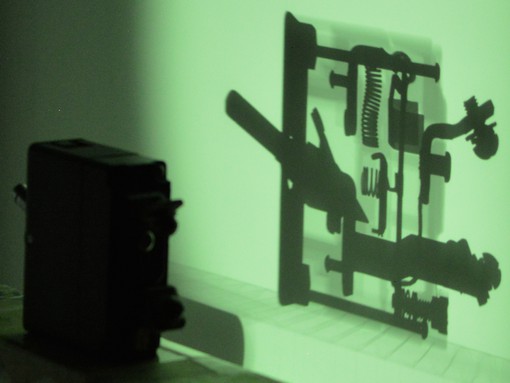
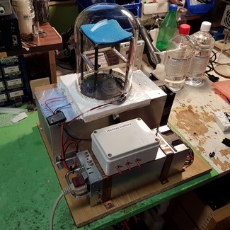 Now let's get to my diffusion cloud chamber construction. This type of cloud chamber is nowadays quite commonly built, whether by pro companies for demonstration purposes, museum pieces or by enthusiasts "at home on their knees" with commonly available materials. Its sizes can vary from large areas somewhere towards 50x50cm produced by profi companies to tiny 6x6cm produced "at home on the knee" by various enthusiasts. The sizes written mean the active area of the cloud chamber.
The shape and size of the diffusion cloud chamber is typically that of a small aquarium or in smaller designs with a glass bell. The size is quite dependent on the cooling method used. Dry ice is used for bottom cooling or, in the electric version, peltier cells. The sublimation temperature of dry ice is -78.5°C. So there is no problem with achieving a low temperature and temperature gradient. It becomes more interesting when using peltier cells, where achieving a low temperature is a bit more problematic. From what I've found, the critical temperature where anything starts to happen in the chamber at all is -25°C. This temperature has to be exceeded, ideally going below -30°C.
The advantages and disadvantages of both types of cloud chambers for home construction with dry ice and electric with peltier cells are probably obvious. Dry ice must always be purchased in advance and will only last maybe a weekend, a few days depending on quantity. With an electric cloud chamber with peltier cells this problem is eliminated, it is always ready for operation, but the only problem is with the more complex construction with peltiers and sufficient cooling of the generated heat. I went into building with peltier cells for a very simple reason, I wanted to have it always ready for operation and experimentation.
The dry ice idea is fine if we were going for a large area for viewing the natural radioactive background on purpose. It's a simple solution, it eliminates a lot of the hassle. But a new problem arises and that is buying dry ice for just a few days.
There are also compressor cloud chambers with a refrigerator cooling circuit, but there is a more complex construction and this variant is mostly realized by professional companies. Or if someone would like to do it at home...
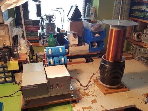
Let's move on to the step-by-step construction of the cloud chamber design, where I will describe the important things about the construction. We're going for peltier cells and our goal is to ideally overcome a temperature of -30°C on the active surface. I have chosen a 10x10cm active area that we want to cool below -30°C.
1. variant with 3pcs peltier cells – 2 stages in cascade
To start with, we will prepare a proper heatsink and peltier cells. Considering that we need to push the temperature of the warm side of the first peltier and therefore the heatsink as low as possible (it's about the difference between the temperatures of the warm and cold side of the peltier), I chose a really massive piece of aluminum (I had free/for postage) and a powerful 12V 4.8A server fan on the side. Realistic draw is 2.1A at 12.5V bought from eBay. Glass bell with a diameter of 14cm and a height of 19cm bought from German Amazon. Plastic screws from RC modelling to reduce heat transfer to the heatsink. Copper sheets I bought 2pcs 10x10cm of 3mm thickness again from German Amazon. One piece is used for the top active area of the 10x10cm and the other cut to 10x6cm for the transition between the peltiers in the cascade from one to two top peltier pieces.
One peltier however powerful is not enough to achieve the required minus temperature ! A minimum of 2 peltiers must always be used in a cascade, but in practice sometimes even this is not enough. As in my case, I did not achieve the required minus temperature in this arrangement. It would be more realistic with a smaller active area (maybe 6x6cm) and using good quality water cooling. Or probably less powerful peltiers in the cascade, to reduce the heat generation that needs to be cooled and thus achieve a lower temperature on the cool side, since it is a temperature difference. The cost will be the longer cooling time required. Anyway, a cascade is always required and 1 piece is insufficient.
Use a suitable heat conductive paste ! Only use processor heat conductive paste with good thermal conductivity. However, too much pressure must not be applied to the peltier cell, as with a CPU, otherwise it may literally burst. A friend of mine has had this happen when tightening screws. So I used springs on the nuts for tightening and didn't tighten completely. In these circumstances, the paste must be suitably evenly spread by hand and therefore, must not be too thick. The first attempt with Noctua paste failed, it is too thick and gaps between the heatsink and the peltier have formed (photo in the album below), this is wrong ! MX-4 paste works well for me, which is thin enough and spread well. As for low temperature and paste, MX-4 does not give me a problem if not exposed to air at such low temperature. What's in between the materials is OK. I have no idea about the durability, Noctua for example gives a temperature down to -50°C but it is not usable due to the density. I consumed 10g of paste, so considering the amount... the price for the paste also decidedly :). We'll see in a year or so... On the other hand, this is not a PC that runs daily. The big problem for the paste turned out to be other things like low temperature, but more on that later in the article.
Another very important thing when stacking peltier cells into a cascade. There must ALWAYS be the most powerful one down on the heatsink and on top of it goes the less powerful and another even less powerful peltier. Either this is solved by the less powerful peltier, or if it is of equal power, by lowering the supply voltage, or a combination of both. I solved it with both a lower power peltier and a lower supply voltage. Also, a larger and more powerful peltier is not always more efficient (power consumption, heat generation/cooling). Most of the time, dimensionally smaller and less powerful peltiers are more efficient at reduced power supply compared to large and powerful ones when reduced voltage is dropped into them. Hence, proper combination and composition of the cascade is necessary. Otherwise, the bottom peltier on the heatsink would not have enough power and efficiency to cool the hot side of the next peltier in the cascade, and then that peltier the next third in the cascade, and so on. The photos below will tell you more, the desired temperature has not been reached, so we move on.
At the end of this first attempt, since I didn't reach the desired temperature, I at least fool around with the transistor at -20°C and create a new type of transistor... CRYOFET ! Otherwise, never freeze new transistors like this, they can get damaged ! At the same time, it was also testing the heat conductive MX-4 paste under the transistor.


https://www.vn-experimenty.eu/en/radioaktivita/difuzna-hmlova-komora.html?filter_tag[0]=21#sigProId275514abe0
2. variant with 5pcs peltier cells – 3 stages in cascade
After the first failure, the choice was clear. It wants another stage up the cascade. In the finale I use these peltier cells (list below) in individual stages in a triple cascade. Between the first and second stage is 3mm Cu sheet, then the peltier cells are 2pc and 2pc directly on yourself. The first 350W peltier goes on a 12.5V supply and the rest are wired in series at half voltage. All the gaps between the peltiers are filled with polystyrene. I had already assumed that this would work, so I tackled the insulation straight away. I use heat conductive paste MX-4 designated for processors. I used a total of 10g of paste. Peltier cells must be used with silicone on the sides, the "S" version. I have a total power consumption of 400W for the peltier cells. For power supply I am using HP 725W 12V 60A and 5V 4A server power supply. All peltier cells go on the 12V branch, real 12.5V. Just look at the photos of the layout and in the result I exceeded the temperature of -32°C. Measuring the temperature with an IR thermometer directly on the Cu sheet made a problem, I had to glue strips of insulating tape for a proper measurement.
- stage: TEC1-12730S 350W 12,5V – 1ks
- stage: TEC1-12715S 150W 6,25V – 2ks (in series)
- stage: TEC1-12708S 85W 6,25V – 2ks (in series)
Peltier cells power input: 400W
Power supply: server HP 725W, 12V 60A, 5V 4A
Heat conductive paste: ARCTIC MX-4
Glass bell: d=14cm; h=19cm (Amazon)
Cu sheets: 2ks 100x100x3mm (Amazon)
Fan: Delta PFC1212DE (eBay)


https://www.vn-experimenty.eu/en/radioaktivita/difuzna-hmlova-komora.html?filter_tag[0]=21#sigProId8b8bc6b7c9
Internal structure, grid, sponge and glass bell
For the construction I used black plastic (polystyrol) rods with diameter 7mm and length 35mm, which I glued together with a hot glue gun. At a height of 8cm above the copper surface is a grid for DC high voltage (1-3kV). Then about another 5.5cm is a piece of PCB attached via nuts in plastic rods. Above is a space for a sponge with isopropyl alcohol (isopropanol, IPA - 99,9%).
Use only glass and no plastic to cover. This is due to the fumes of isopropyl alcohol. A silicone LED strip (natural white, 120 LED/m, waterproof) is attached to the glass itself, which is glued together again with a melt gun and only sticks to the glass through the silicone and can be freely moved and changed in height.
It is good to make the copper surface all black because of the good visibility of the particle trajectories in the fog and the reflection of the light. Some people use various black thin foils, but I haven't found anything suitable at home. Black insulating tape has also proved to be a workable solution and quite good enough. I'd probably prefer to avoid foil, and the ones at home were all too thin, showed through, crinkled, and weren't even black enough. Beware of unsuitable paints and varnishes for sub-zero temperatures and isopropyl alcohol. In the end, the electrical insulating tape worked best during testing anyway.


https://www.vn-experimenty.eu/en/radioaktivita/difuzna-hmlova-komora.html?filter_tag[0]=21#sigProId28d376a241
HV source for grid
The high voltage DC source for the grid should be in the range of roughly +1 to +3kV. This is dependent on the size of the cloud chamber and the distance of the grid from the surface, so experimentation is needed to test the appropriate voltage size. I currently use +1.2kV. The positive voltage goes on the grid and the ground connects to the copper surface below.
As many of you may have noticed, not everyone uses an HV source in the cloud chamber and actually it is not even necessary, but with the voltage on the grid the cloud chamber just works much better and the visibility of the particles is improved. This is without a doubt and here are the following explanations, hopefully correctly theoretically described. A demonstration video of the effect of the +1.2kV voltage in the chamber is also attached.
- The voltage on the grid affects the trajectories of the particles. The particles will be pushed by the field into the horizontal plane along the surface through the saturated alcohol vapour. Of course, with regard to the magnitude of the voltage, the distance of the grid from the surface and the energy, speed and mass of the particles themselves. Then also given the size of the active viewing surface, if at all, there will be time and space, for a visible effect on the trajectory of the particle. There will be an effect on the slow low energy ones, and it is realistically visible. The particles will be more in the area over the entire alcohol saturated vapor area. The effect of the +1.2kV voltage can be seen beautifully near the perpendicular conductor to the surface going sideways to the grid. Nice to see in some of the photos further down in the article how the positive alpha particles are repelled, the direction of the trajectory changes, or even nicely follows the particle arc through the voltage field of the conductor. Some particles will in turn pass through or only slightly change their trajectory. It depends on the energy and momentum of the particle.
- The voltage has an effect on the formed ions in the gas from the particles. As an electrically charged particle flies through a cloud chamber, it ionizes its surroundings and ions are produced. However, these ions are also affected by the electric field from the grid. If such ions are formed just above or below the alcohol saturated vapor area, then the field due to polarity will attract/repel them and they can get right into the alcohol saturated vapor area. This will immediately pack alcohol droplets onto these condensation nuclei and make the trajectory of the particle visible. At the moment of condensation of alcohol vapours, the electric field ceases to affect these droplets, they become neutral and fall down due to gravity.
- The voltage on the grid polarises the alcohol vapour. This drastically increases the chances of vapor condensation on the ions as they are electrically attracted. Ions that leave particles flying in their wake, especially high-energy fast particles like electrons and muons, behave as very attractive condensation nuclei for alcohol vapor. It is also because of this that their trajectories become clearly visible in the fog. Alphas and protons become even more visible and denser. Something similar can also be achieved by faster evaporation of alcohol. Also, it can be seen with the naked eye on the alcohol vapor, according to the amount of voltage, the fineness and density of the saturated vapor particles changed visibly. With the appropriate voltage on the grid, the particles were more visible and had sharper contours in the fog.
Conclusion from observations. If is no voltage connected to the grid. The visibility of the particles is poor. The alpha particles were "blurry" and I could hardly even see the electrons. Not to mention muons and generally fast high energy particles.
After connecting the +1.2kV voltage, I suddenly saw a much larger number of particles, the particles reached longer visible paths more in a straight line. The heavy alpha particles of the helium nucleus gained sharper and brighter contours in the fog. And I could already see low energy, medium and high energy electrons and fast muons beautifully sharply. I was able to see sharp and clear lines in the fog.
Finally, I tested even higher voltages above +2kV up to +3.5kV from the HV source from the plasma ball. However, the result was already bad. The character of the saturated vapours and their structure changed visibly, I stopped seeing electrons and muons. Only the heavy helium nuclei remained visible, but the trajectories started to blur. Apparently I had disturbed the formation of the saturated vapor downward, changed the pressure and shifting the vapor more upward toward the grid by overvoltage.
So yes, voltage is important, but not a requirement (but why not use it ?). At least for polarization of alcohol vapor and thus increasing the visibility of particle trajectories and increasing the sharpness of contours. There is also a visible effect on the particle trajectories or the effect on the ions in the gas that have been shifted to the saturated vapor area. The question is which effect is more prevalent or is it simply a combination of everything together. It also comes down to the total observing area and energy with the momentum of the particles, which is not small. The magnitude of the voltage needs to be experimented with. Below are photos of the HV sources from testing and a video demonstration of the chamber, first with no voltage and then I turn on the +1.2kV HV source on the grid. Nice to see the difference. In the video for the demonstration a sample of the uranium mineral Autunite was used. Later on in the photos below at the alpha particles you can see the effect of the electric field beautifully.
HV source up to 1.2kV: eBay


https://www.vn-experimenty.eu/en/radioaktivita/difuzna-hmlova-komora.html?filter_tag[0]=21#sigProIda3aa9ceabf
Top heating in the chamber
Heating the top of the chamber helps the cloud chamber very effectively. This is for two reasons right away, it will increase the temperature gradient of the top and bottom of the chamber plus the higher temperature will speed up the evaporation of the alcohol from the sponge. Faster alcohol vapor supply means better particle visibility in the saturated alcohol vapor layer. Plus add to this the high voltage polarization of the alcohol vapor described above and the result is excellent. I am currently using an improvised 100W halogen in a table lamp from above on glass, which can be seen nicely in the videos.
28.12.2020
Just two days after the article was published, I completed the additional heating upgrade. Rather than heat it improvisationally with bulb/halogen from above, I did internal heating via power resistors. It's a minor little thing. But I had no idea how significant the change would be. Given the circumstances, I have added and modified some information in the article from new knowledge to make it all together and not just some update at the end of the article.
I solved the heating quite simply, I built a series resistor snake with 4x TR224 18R/2W. Total 72R/8W at 12.5V. I didn't deal with any regulation and as I found out it is not even necessary in my case. The resistors are sealed in heat shrink tube and loosely laid on the sponge. I measured the temperature just above 60°C. I turn on the cloud chamber and the heater at the same time, I leave the heater turn on permanently.
By starting to heat permanently the upper compartment of the chamber with a steady temperature of the resistors and directly on the sponge with isopropyl, I achieved a rapid evaporation of alcohol. I increased the temperature gradient and more importantly more stable temperatures and more stable conditions in the cloud chamber. The silicone groove around the glass also plays a role in this for a better seal inside. It's noticeable in the change in behavior of the saturated alcohol vapor layer.
The conclusion of all this in practice. The saturated alcohol vapor area is more stable and has a faster alcohol vapor supply. The dead time of the area has been reduced, that is, by one particle flying by, for example, even a large heavy alpha particle that takes a very large number of alcohol vapours with it, the area in question recovers quickly and is able to detect and capture the next and the next particle. The number of observable particles in the chamber has also increased. Currently, even with a larger shower of alpha particles from a uranium mineral, I am able to observe quite clearly and many surrounding electrons that have thin trails. Reducing the dead time and increasing the density of observable particles ! But that's still not all, the resolution of the particles has increased and only from now on I am able to distinguish protons !


https://www.vn-experimenty.eu/en/radioaktivita/difuzna-hmlova-komora.html?filter_tag[0]=21#sigProIdaf38dbd081
Almost done...
Photos of the almost completed cloud chamber and its temporary state. The wires from the HV source to the grid are teflon insulated, voltage resistance is OK. All classically fixed on a piece of wood board from what the "house gave". And why almost done ? .. the vast majority of the photos and videos in the article are taken with the cloud chamber designed like this, as in the photos. Well after a few days of experimenting and a few days of the chamber standing on the table, after turning on the problem, the chamber did not work... about it in the next paragraph.


https://www.vn-experimenty.eu/en/radioaktivita/difuzna-hmlova-komora.html?filter_tag[0]=21#sigProIdceeca9618e
Rebuilding of the entire cloud chamber contruction and Finalization
After all the experiments with the cloud chamber, which are mostly here on the web in the article and already during the writing of the article, in a few days of not using the chamber after turning it on it just stopped working. I measured the temperature and couldn't get below 0°C. The temperature was still around 1°C.
What happened. The isopropyl alcohol overflowed around the Cu sheet down on the heat sink to the peltier cells. I only solved the peltier cascade electrically to make it waterproof, but I had no idea that the IPA would completely destroy and dry out all the heat conducting paste under the entire peltier. It only destroyed it on the first one (both sides of the peltier), the rest of the upper stages of the cascade were OK. Also, the fumes have etched the polystyrene. I had to completely disassemble the whole cascade, during disassembly the lower peltier literally fell off under its own weight with dried paste. I cleaned the whole thing completely, reapplied MX-4 paste and put the whole cascade back together with a few changes.
The second and third stages of cascade, where the peltiers are side by side, I put silicone between them. The heat conductive paste squeezed between the peltier cells and made a warm conductive connection from top to bottom across the two stages of peltier cells. I filled the given space with silicone and glued them together. Having a cross pass over the peltier cells like that with the heat conductive paste is also quite a big problem.
I used new cut polystyrene that had silicone going everywhere. I made the entire peltier cascade in the polystyrene and polystyrene itself completely resistant to liquids and vapors. I also thoroughly sealed with silicone the transition Cu sheet and polystyrene. The silicone is elastic and also for use in sub-zero temperatures.
The wires from the HV source (+1.2kV) to the grid are already routed crosswise through the polystyrene and not under the glass bell for easier work, takeaway the glass and insulating the inside of the chamber. All sealed again with silicone.
The glass bell has a silicone groove around on the base for the glass where it fits nicely. I soaked the glass in soapy water and inserted it nicely into the prepared silicone on the base, molded the silicone onto the glass and then just twisted it out. This is to better insulate the inside of the chamber, to keep the alcohol vapours in there and not create blow-by under the glass. It can also be seen in the behavior of the saturated fog in area.
The LED strip is now no longer on the glass, but placed in close proximity to the glass and fixed with silicone in the base. Because of the elasticity of the silicone, it is pliable and beautifully the glass bell inserts into the groove and also takeaway. It's more comfortable this way and especially when cleaning the glass.
Insulating tape remains as the best option for Cu sheet. I also tried black nail polish (someone was using it, so I tried it), but it was a total crap. Not only did the isopropyl alcohol etch the varnish, that was even less of a problem, the reflections from the surface was a problem. Still the electrician's insulating tape remains, as the best option for black enough color, frost resistance and isopropyl alcohol plus hassle free replacement with a new piece of tape. And even though the insulating tape doesn't look the prettiest in the last photo, once a layer of isopropyl alcohol is created on the tape, most things are lost, but mainly the reflections and glare are broken, which are the worst for visibility.
After the rebuilding with these changes, I reached temperatures as low as -38°C after subsequent testing ! Next, just photos of the whole rebuilding and finalization of the Cloud Chamber.


https://www.vn-experimenty.eu/en/radioaktivita/difuzna-hmlova-komora.html?filter_tag[0]=21#sigProId8c39a6c331
The additional completing of internal heating resistors, as just such a triviality for convenience. Which turned out to be a very strongly substantial thing. More detailed information in the previous paragraph top heating in the chamber. Here just the rest of the photos.


https://www.vn-experimenty.eu/en/radioaktivita/difuzna-hmlova-komora.html?filter_tag[0]=21#sigProId3e84a7d8ab
What particles can we see there ?
Only electrically charged particles can ionize their surroundings during their orbit and thus produce ions. A particle flying through an unstable saturated vapour creates ions in its surroundings. These behave as condensation nuclei and, due to the instability of the vapour in that space, the unstable vapour goes into a liquid state and condenses precisely on the formed ions along the particle's trajectory. Sufficient strong illumination and a black surface maximizes the visibility and contrast of the particle trajectories in the fog. Then, according to the size, energy and momentum of the particles, characteristic traces appear in the fog, discussed later in the paper.
We can see: alpha (He2+), protons (p+), electrons (e-), positrons (e+) and muons (μ+/-)
Alpha (α) radiation is helium nuclei, two protons and two neutrons.
Beta radiation is electrons (β−) and positrons (β+).
Neutral particles (neutron, gamma, X-ray) can be detected indirectly by charged particles that will be produced in the fog after their interaction - photoelectric effect [ Wikipedia ], Compton scattering [ Wikipedia ] etc.


https://www.vn-experimenty.eu/en/radioaktivita/difuzna-hmlova-komora.html?filter_tag[0]=21#sigProIdc0e3f85057
Alpha particle
It is a helium nucleus (He2+), it has two protons and two neutrons with a positive charge of +2e leaving short and fat trails in the cloud chamber. The stream of alpha particles is called alpha radioactive radiation. It is the least penetrating radiation, it is stopped by a sheet of paper and also by the epithelial tissue of the human skin surface. However, the source of the alpha particles may not enter the human body, for example, the lungs or by eating.
Natural sources of alpha radiation are, for example, uranium, radium or radon. The radon isotope 222Rn is known for its potential to accumulate in the basements of buildings, and is commonly released from the earth's soil. An example of an artificial source of alpha radiation is the americium isotope 241Am, which does not occur in nature. In a cloud chamber we can observe radon (222Rn) decay in the natural background. Below are a few frames from a video of the cloud chamber from the alpha particle observations. In some of the photos we can see the influence of the electric field near the vertical conductor with +1.2kV for the grid.
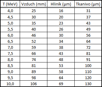
For interest, here is a table of the reach of alpha particles through materials according to their energy. As you can see, at my active area of 10x10cm some alpha particles can cross the whole chamber at high energy.
In the table, columns from left to right: air, aluminium, human tissue.


https://www.vn-experimenty.eu/en/radioaktivita/difuzna-hmlova-komora.html?filter_tag[0]=21#sigProId9a94541ee4
Electron and positron
Electrons (e-) are a variety of thin, short or long, zigzag or straight tracks in the cloud chamber. It is these tracks that we see most in the chamber. How much an electron's trajectory bends depends on its energy. The lower the energy, the so-called low energy electrons, their trajectory will be short and very twisted with collisions. Then, as the energy increases, we have so-called medium energy electrons, where the trajectories are longer, more balanced but still twisted and with collisions. Finally the high energy electrons, which take long sometimes almost straight paths through the chamber and can be confused with a muon with a small viewing area. Which is already the case for me.
The electrons in the cloud chamber originate either from radioactive transformations (decays) carried out on the ground, i.e. as part of the natural radioactive background, or from secondary cosmic rays, e.g. from muon decays.
The stream of electrons is referred to as beta-minus (β−) radiation. It is more penetrating than alpha radiation and can be shielded by, for example, a 1mm lead plate.
Positrons (e+) are the antiparticle of electrons, it is a particle of antimatter. The footprint of a positron is identical to that of an electron. The first positron was just discovered in an expansion cloud chamber (Wilson cloud chamber). The only way to distinguish between electrons and positrons is to place the chamber in a magnetic field, where the electron and positron will spiral in opposite directions.
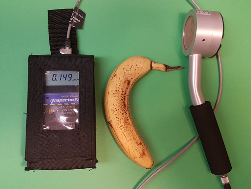
Again, the observed positrons in the cloud chamber originate from natural decays on the ground or from cosmic rays, e.g. from the decay of antimuons. An example of a natural source of positrons is the decay of the potassium isotope 40K, which is most abundant in bananas.
The positron stream is referred to as beta plus (β+) radiation.
When an electron and a positron collide, they annihilate, the original particles disappear, and a pair of gamma ray photons with an energy of 0.5MeV is produced. The photons spread away from each other in opposite directions.


https://www.vn-experimenty.eu/en/radioaktivita/difuzna-hmlova-komora.html?filter_tag[0]=21#sigProId5a28afdd0a
Proton
Proton (p+) forms a distinct trail that can often span the entire surface of the cloud chamber. The proton trail can be across the entire viewing area, a shorter line, or just a dot, depending on the angle at which the proton passes through the cloud chamber. Protons originate in cosmic rays. Most of the trajectories shown will be, as a short line at an angle from above.
I can beautifully determine and observe protons only after solving the internal heating by resistors. For more details why this is so, I write here about the top heating in the chamber. Just briefly, heating the inside of the chamber with resistors greatly increased observability, particle resolution, and reduced the dead time of the area. More details are in the previous paragraph, here just photos of the protons.
I recommend to go through the gallery of proton photos from the beginning to the end. In the description of the photos is written the order of frames from the total number of consecutive frames from the video. Nice to see the progression of the trail proton in the fog even with other alpha particles.
- (Fig.1-6) Note the first series of six photos. Nice to see how the proton passes through the 3mm copper at an angle, see the clear trajectory. At the same time see the fog from the alcohol vapor above the proton trajectory. This is just the effect of the electric field on the ions in the gas that have been drawn into that area of saturated alcohol vapor. The trajectory is shown even though the real proton passed outside at an angle, without the electric field and with a voltage of +1.2kV on the grid this would not have been possible.
- (Fig.7) The same case is figure number 7, where only a short trajectory of the proton at an angle is seen. But the trajectory in the fog, just like a blur, is considerably longer and follows the trajectory of the proton that was already over that area. The electric field pulled the gas ions into the saturated vapor area and condensed the alcohol vapor into condensation nuclei, i.e., ions.
- (Fig.8-10) A nice comparison of a single proton at the center and the surrounding alpha particles. A couple of consecutive frames from the video to better understand and show the event.
- (Fig.11-12) A literally perfect photos of a proton flying right through the saturated vapor area, leaving a beautiful bright thicker proton trail. Nicely distinguishable from electrons and alpha particles. Eventually the fog trail falls down through gravity and disappears.
- (Fig.13-14) A nice example of a proton flying through a chamber at an angle. Seen the trajectory of the proton and the rest of the fog created by the electric field pulling the ions into the area. Then in the second photo, you can see the entire fog trail already falling down by gravity.
- (Fig.15-30) The remaining individual photos of protons. The vast majority of the photos are of protons at a top-down angle through the chamber. The protons come from cosmic rays, so most of them pass at an angle, like a line. But for a long time I couldn't discern and distinguish them enough in the chamber.


https://www.vn-experimenty.eu/en/radioaktivita/difuzna-hmlova-komora.html?filter_tag[0]=21#sigProId079db4ff5d
Muon
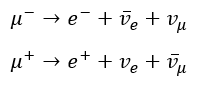
The muons (μ+/-) are produced by the interaction of cosmic rays with the atmosphere and penetrate to the Earth's surface, where they can be observed in the cloud chamber. Their lifetime is too short, only 2.2µs. But thanks to time dilation, as they move at close to the speed of light (special relativity), they manage to reach the Earth's surface before they disintegrate.
The decay of a muon (µ-) produces an electron (e-), a neutrino (vµ) and an electron antineutrino or the decay of an antimuon (µ+) produces a positron (e+), an antineutrino and a positron neutrino (ve). For antineutrinos, the web does not take that special character – see mathematical notation below.
Down in the photos it could be the muons photographed. Thin straight fast flying particles through the cloud chamber. At worst, some of it will be a high energy electron. A high energy electron and a muon are easily confused and especially with such a small active chamber area.


https://www.vn-experimenty.eu/en/radioaktivita/difuzna-hmlova-komora.html?filter_tag[0]=21#sigProId0e53e9ca06
Decay of the muon
In a cloud chamber, with luck, it is also possible to observe the decay of a muon by a weak interaction on an electron. This decay is observable from the course of the fog trail. The thicker trace of the muon suddenly bends sharply and becomes thinner, the muon has decayed and we observe a thinner trace of the electron. The other particles, the muon neutrino and electron antineutrino, are not observed in the cloud chamber because they are not electrically charged.
The photo below is probably a theoretical capture of the muon decay, but again it would require better observability and a larger area. Plus a description of the decay of the muon (µ-) and antimuon (µ+) into the electron (e-), positron (e+) and neutrino.

https://www.vn-experimenty.eu/en/radioaktivita/difuzna-hmlova-komora.html?filter_tag[0]=21#sigProId975f5de682
Radon-220 gas decay
The V-shaped traces belong to two alpha particles that were emitted very shortly close together. If we splash radon 220Rn gas into the cloud chamber, we observe its decay (half-life 55.6s) to polonium 216Po, which almost immediately decays (half-life 0.145s) to lead 212Pb. These two decays are accompanied by the emission of two alpha particles, which we observe in a V-shape. The decay of Radon-220 follow the thorium decay series.


https://www.vn-experimenty.eu/en/radioaktivita/difuzna-hmlova-komora.html?filter_tag[0]=21#sigProId57bbd9a500
I obtained the gaseous Radon-220 isotope (220Rn) from a thorium mantle for gas latern lamp. In the syringe the gas accumulated and in a few minutes I could spray it with a needle into the cloud chamber. The substance contains thorium oxide (ThO2), which tolerates very high temperatures to protect the substance. The melting point of thorium oxide is as high as 3300°C, one of the highest of all known oxides.


https://www.vn-experimenty.eu/en/radioaktivita/difuzna-hmlova-komora.html?filter_tag[0]=21#sigProId11fd7df982


https://www.vn-experimenty.eu/en/radioaktivita/difuzna-hmlova-komora.html?filter_tag[0]=21#sigProIda6c82e7a50
Mix of different particles displayed simultaneously on the area


https://www.vn-experimenty.eu/en/radioaktivita/difuzna-hmlova-komora.html?filter_tag[0]=21#sigProIdc5612e2f6d
Video of cloud chamber + natural background
The video was filmed and edited in the initial version of the cloud chamber without silicone insulation.
At the end of the video is a demonstration of the natural radioactive background. After the rebuilding, I added silicone on polystyrene everywhere so that no liquid and moisture could reach the peltier cells. Plus added silicone between the peltier cells placed side by side so that the heat conductive paste doesn't get between them and create a top to bottom heat conductive column of paste.
Live with the naked eye the visibility of the traces is better and more beautiful, but shooting a video of such a small 10x10cm active area up close illuminated by a bright white LED strip is not much fun.
Radioactive objects and uranium minerals in the cloud chamber
Uranium minerals: Uraninite + Autunite
Uranium minerals, see here for more details on the minerals themselves. In some of the photos you can also see the decay of radon (3 photos, V-shape). Autunite is a more strongly active fluorescent uranium mineral that glows under UV light (395nm, 365nm...). The bottom row of photos belong to the second video, they are small samples of pebbles containing uraninite from the Czech Republic.
Depending on the mineral size, surface area and activity, a predominance of alpha or beta particles can be seen. The larger the mineral with more surface area and the more active, the more alpha is active and the more alpha particles overwhelm the chamber with thick traces. Then the thin lines of beta particles will remain unseen. The smallest possible mineral sample is required to dominate the imaging of beta particles. Such a mini sample will then only occasionally "spit out" alpha particles and the visibility of beta particles will be predominant throughout the chamber (second video).
The ideal would be to have an active area the size of a fishbowl, then the path of the alpha particles (He nuclei) would be only a few cm and in the remaining area the beta particles (electrons) would be beautifully visible.


https://www.vn-experimenty.eu/en/radioaktivita/difuzna-hmlova-komora.html?filter_tag[0]=21#sigProId3d1346f1a6
Strontium-90, Americium-241 and Uranium glass
Strontium-90 (90Sr) is a pure beta emitter, in the video and photos you can see the shower of electrons from the emitter. Americium-241 (241Am) is the alpha emitter from the fire detector. Nice to see low energy alpha particles shooting out to a short distance compared to Radon-220. 241Am is also a weak low energy gamma ray emitter (59.5409keV). Uranium glass has alpha, beta and gamma decay. More details on the emitters here.


https://www.vn-experimenty.eu/en/radioaktivita/difuzna-hmlova-komora.html?filter_tag[0]=21#sigProId8e8cf19080
This second series of photos with 241Am emitter was taken later with the addition of internal heating. Note how the imaging of the particles in the chamber has changed and how the number of particles imaged has increased. At the same time, somehow more low energy electrons started to appear around 241Am. More on their origin further down here (gamma photon interaction).


https://www.vn-experimenty.eu/en/radioaktivita/difuzna-hmlova-komora.html?filter_tag[0]=21#sigProId28db85a18d
10.7.2021
Same case as in the photos above, but under different internal conditions in the cloud chamber and a different piece of the more active 241Am emitter. The video of this case is at the very bottom of the article.


https://www.vn-experimenty.eu/en/radioaktivita/difuzna-hmlova-komora.html?filter_tag[0]=21#sigProIdbb41f57502
Tungsten rods with 4% thorium
10.7.2021
Small tungsten rods with 4% thorium from TIG welding electrode. Ideal sticks for cloud chamber, TIG electrodes are still relatively easy to get hold of. They have alpha, beta and gamma decay. The two pieces in the photo give 1.2uSv/h. The images are from the video at the very bottom of the article.


https://www.vn-experimenty.eu/en/radioaktivita/difuzna-hmlova-komora.html?filter_tag[0]=21#sigProId32d4cf5c57
Interaction of electromagnetic radiation – X-Rays and gamma rays in a cloud chamber
X-ray experiment with the DY86 rectifier vacuum tube. For this experiment, even a weak X-ray source, like an ordinary diode connected in reverse to a high voltage source roughly up to +30kV from a multiplier, will suffice. Hastily wired on the table, classic this HV source, then cascade multiplier from the TV and straight to the DY86 diode laid on the books next to the cloud chamber glass.
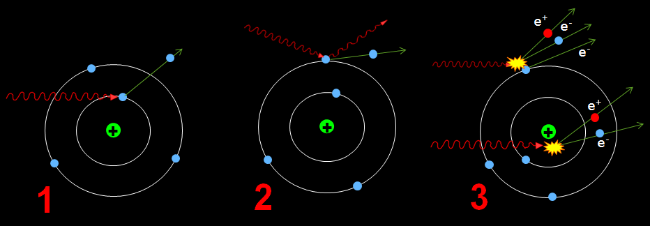
Photons are neutral particles (radiation) and thus cannot in any way ionize the gas atoms in the space of the cloud chamber. They can only be detected indirectly by charged particles that will be generated in space and their subsequent interaction with the gas in the chamber.
Electromagnetic radiation can interact in matter according to three main processes:
- Photoelectric effect [ Wiki-EN ]
- Compton scattering [ Wiki-EN ]
- Formation of electron-positron pairs [ Wiki-EN ]
Note: Point #3 will not be realistic in this case with such a weak X-ray. The first two phenomena will take place.
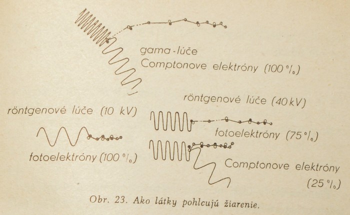
Excerpt from Radiation and Life (1959), (Slovak language):


https://www.vn-experimenty.eu/en/radioaktivita/difuzna-hmlova-komora.html?filter_tag[0]=21#sigProId093ba470c0
Due to the comprehensiveness of the issue, further information only from the attached sources. Further only photos and video from the experiment. In the photos and video you can see the shower of electrons in the cloud chamber by bombarding the material with photons from the X-ray source from the DY86 diode.
Warning, the experiment works with ionizing X-rays !


https://www.vn-experimenty.eu/en/radioaktivita/difuzna-hmlova-komora.html?filter_tag[0]=21#sigProIdf6955eb674


https://www.vn-experimenty.eu/en/radioaktivita/difuzna-hmlova-komora.html?filter_tag[0]=21#sigProIdf3260f7a58
30.12.2020
In addition Americium-241 to being an alpha emitter (α decay: 5.486MeV) is also a weak gamma-ray source (γ emission: 59.5409keV). As in the X-ray experiment performed above, the same phenomenon can be achieved with 241Am, but with essentially smaller scale and observability. I only noticed this by sheer coincidence when isopropyl alcohol got a larger amount directly on 241Am and thus shielded the alpha particles. Only gamma was penetrating and without the alpha particles present, it was possible to observe low energy electrons being produced in the area due to the presence of gamma rays.


https://www.vn-experimenty.eu/en/radioaktivita/difuzna-hmlova-komora.html?filter_tag[0]=21#sigProId7ce46edae7
24.3.2021
Repeating the same experiment, now experimentally with 4x 241Am taped over with insulating tape. It's best to see it on video anyway, like this in the photo. The cut in question is in the final video at the bottom of the article.


https://www.vn-experimenty.eu/en/radioaktivita/difuzna-hmlova-komora.html?filter_tag[0]=21#sigProIdbdaccbbf71
10.7.2021
Again another repetition of the same experiment, but this time with up to 12x 241Am stacked around the active area. Taped over with insulating tape to shield the alpha particles. Again, this experiment is better viewed in the video located at the very bottom of the article.


https://www.vn-experimenty.eu/en/radioaktivita/difuzna-hmlova-komora.html?filter_tag[0]=21#sigProId8d3398ca87
Final video compilation of the whole cloud chamber project
Video cut the final diffusion cloud chamber from the construction itself, photos describing basic design information to demonstrations and experiments with the chamber. Demonstrations of the natural background of radioactive decay, cosmic rays, descriptions of individual particles in the chamber to various radioactive objects, minerals, radon gas and finally the interaction of X-rays and gamma rays in the cloud chamber.
10.7.2021
Another video, as a continuation of the previous one. The video shows only purely different radioactive objects and minerals in or next to the cloud chamber. The video shows different sizes of Uraninite, Autunite next to the chamber, tungsten rods with 4% thorium admixture, 241Am, 90Sr next to the chamber, injected radon 220Rn and finally the interaction of gamma photons in the chamber from 12pcs of 241Am stacked around the active area. Some frames from the video of the new subjects are also added and scattered throughout the article.